
Research Multiphase and index-matched flows
Solids do not go where the flow goes
Pipelines carry sand, catalyst, ice and debris, and the rules used to size them treat those solids as passengers that follow the fluid. A particle with enough inertia does not. Where the bore changes, the fluid reorganises and the solid keeps its own momentum.
Time-resolved tomographic particle tracking
The question
An area change is where the two part company
Fittings are sized for fluid alone. Much of what a real pipeline carries is not fluid.
Sand in an oil line, catalyst in a reactor loop, grit in a water main: pipelines rarely carry one clean phase. Where the bore changes, the fluid reorganises within a diameter or two and a solid particle cannot. It crosses streamlines, runs into walls, and can sit for a long time in fluid that is going nowhere.
What that costs in pressure and in wear is handled by correlations fitted to pressure readings. Almost none of them rest on watching where the particles actually go.
The design rules are old. The measurement is new.
How we see it
Make the pipe and the spheres disappear
A curved wall bends light. A solid sphere blocks it. Index matching removes both at once.
Optical measurement inside a round pipe fails twice over. The curved acrylic wall acts as a lens, so a particle is never quite where it appears to be, and a solid sphere in the way throws a shadow across everything behind it.
Both problems vanish if the liquid bends light exactly as much as the acrylic does. A concentrated sodium iodide solution does, so the pipe and the spheres in it become invisible and four high-speed cameras can look straight through at the tracer particles. The same trick carries our work on freely rising spheres and on pipe expansions.


For the specialist
Four Phantom v2640 cameras on Scheimpflug adapters, recording at 8,800 Hz over a 64 × 40 × 30 mm volume at a magnification of 33.16 pixels per millimetre. Each run holds 10,000 consecutive fields, a continuous record of 1.14 s. Particle tracking with Shake-The-Box in DaVis 11 gives a final vector spacing of 483 µm.
Two obstacles to seeing, removed by one liquid.
What the cameras record
Both area changes, on the same rig
One camera's view, lit by the laser volume. Flow runs right to left in both clips.
Nothing between the cameras and the flow.
What comes out
Every tracer, tracked
Tens of thousands of individual particle paths, in every frame, through the whole volume.
The two regions meet along a sharp boundary rather than a gradual one. The core carries on as though the narrow wall were still there; the fluid beside it has been left behind. A sphere that stays in the core is through in milliseconds. A sphere that strays out of it is in no hurry to leave.
The flow splits in two, and the solids have to choose.
First look analysis in progress
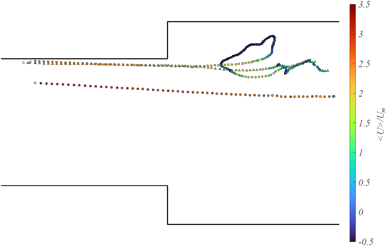
Some cross, some get caught
Sphere paths from three runs, seen in the volume and in the three views through it.

This is as far as the analysis has gone, and it is already the interesting part: a path that loops has spent time in fluid that was going nowhere, which is where wear, settling and blockage begin.
Pulling the sphere out of ten thousand consecutive volumes, and measuring the flow in the millimetre of liquid around it, is the work in front of us. The reconstruction we built for moving bodies was written for exactly this: a solid travelling through the measurement volume, which ordinary reconstruction quietly fills with a flow that is not there.
The recording is done. Reading it is the work in front of us.
Work with us
A recorded dataset that nobody has finished reading is a good place to start a thesis.